-
Electronics
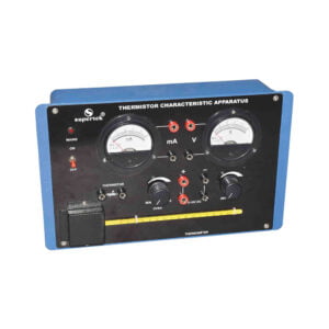
Thermistor Characteristics Apparatus
This instrument is designed to plot the negative resistance co-efficient characteristics of a thermistor. Instrument comprises of variable DC Regulated Power Supply 0 – 10 V DC (150mA). Two digital meters for voltage and current measurement. One thermistor is kept in Oven. Connections of supplies, meters, and thermistors are brought out at 4 mm Sockets. 4mm stackable lead and instruction manual are also provided with the instrument.
PH92168 -
Electronics
LCR Impedance Apparatus
This instrument is designed to calculate the AC power factor of an LCR circuit when connected in series. Instrument comprises of variable AC Power Supply 0 – 15 V AC. Two AC moving coil meters one for voltage and current measurement are provided on the front panel. 2 Resistance, 2 Capacitors, and 1 Inductance are inside the panel and connections are brought out at 4mm sockets. 4mm stackable lead and instruction manual are also provided with the instrument.
PH92172 -
-
Electronics
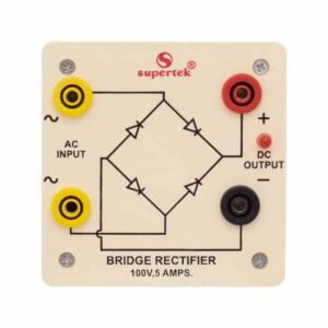
Bridge Rectifier
Bridge Rectifier is made of four diodes connected in a bridge circuit. It is housed in a plastic moulded box. This bridge rectifier converts alternating current (AC) into direct current (DC). It provides the same output polarity for either input polarity. All electronic devices require direct current, so bridge rectifiers are used inside the power supplies of almost all electronic equipment. For an easy understanding of the internal circuitry, the circuit diagram is printed on the box.
PH92352 -
Electronics
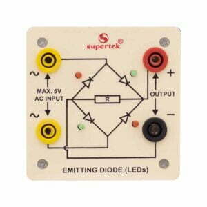
Emitting Diode (LED’s)
The bridge rectifier is designed with four LED’s internally arranged in a bridge pattern fitted inside a plastic moulded case. Two LED’s are red and two LED’s are green. This device is used to demonstrate the functioning of a bridge rectifier, i.e., to convert alternating current (AC) into direct current (DC). Two yellow sockets are used for AC input. Two sockets, one red, and one black are used for DC output. For the easy understanding of the internal circuitry, the circuit diagram is printed on the box.
PH92354 -
Electronics
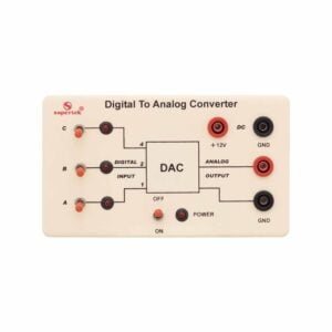
Analog to Digital Converter
The ADC unit converts an analog signal to a digital signal. When a variable voltage is applied to the input terminals it is converted into a digital output. Therefore, a 3-volt input will correspond to binary 11, and 7 volts will correspond to binary 111. A low-frequency AC input signal can be converted into a changing digital value. Use on its own or combined with the DAC to decode back into a stepped analog voltage.
PH92370A -
-
Electronics
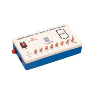
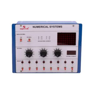
Numerical System
This panel is used to demonstrate the number systems such as binary, decimal, and hexadecimal numbers. Toggle switches are used to activate the displays showing the particular number entered. Input may be entered either as decimal or binary numbers with a toggle switch for mode selection. Decimal numbers are shown on a three-digit seven-segment LED display. Operates on 220V.
PH93002 -
Electronics
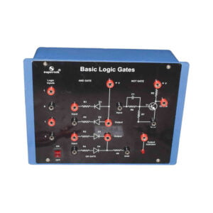
Logic Gates Trainer
Logic Gates Trainer is a self-training course in basic digital electronics and is the first step to understanding the fundamentals of any computer. It enables the student to understand AND, OR, NOT, NAND & NOR Gates and in the process to make connections. Supplied with user’s manual.
PH93005 -
Electronics
Logic Gates Trainer
Logic Gates Trainer has been designed to study logic gates and applications. This trainer board is designed to verify the truth table of various logic functions, to prove De-Morgan’s theorem, Half adder, and Full adder by using logic gates. The board is absolutely self-contained and requires no additional apparatus. 12 V / 1 A DC adaptor is required to operate it.
PH93005B -
Electronics
Logic Gate Circuit Trainer
Study and verification of flip flops, counters, shift registers, encoders, decoders, multiplexers, and de-multiplexers. Consists of 8 debounced logic inputs, 8 red LED output indicators, +5 V DC (1 A) regulated, short circuit and overload protected power supply, and 1 Hz mono shot clock pulse. All the ICs and components have been placed inside the cabinet and connections brought out at 4 mm sockets.
PH93007 -
Electronics
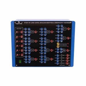
Study of Logic Gates, Boolean Identities and Demorgan’s Theorems
To verify the truth table of 3 input AND gate, OR gate, NAND gate, NOR gate, single input NOT gates, Boolean expressions, and Demorgan’s theorems. Consists of 5V d. c. regulated power supply, 4 push-to-ON switches provided for selecting logic ‘1’ and logic ‘0’, 2 Red LED output indicators, circuit diagram printed for 5 OR, 5 AND, and 4 NOT gates and their respective IC’s placed inside the cabinet and connections brought out at sockets.
PH93010