-
Electronics
Operation Amplifier Kit
To study Operational Amplifier Characteristics and Applications. Consists of 3 D. C. regulated power supplies of 0 – 5 V Continuously variable, ± 15 V D. C. regulated power supply, Sine, Square, Triangular wave outputs, one Bread board having two main strips and two distribution strips. Complete with two dual-range meters and necessary components.
PH93015 -
Electronics
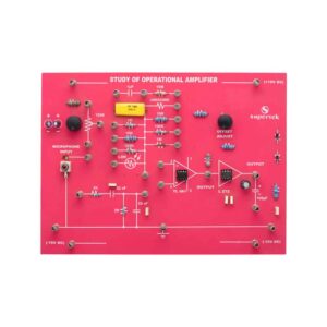
Study of Operation Amplifier
To demonstrate the function of the operational amplifier using TL081 and L272 with discrete components with different values of resistors, and capacitors. Input can be applied from the microphone and LDR. Offset null control is also provided. Output can be fed through the power amplifier into a loudspeaker.
PH93020 -
Electronics
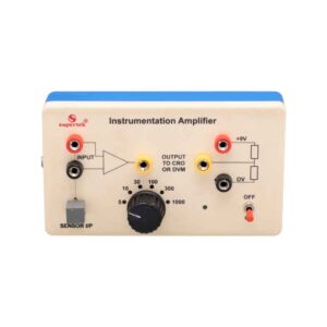
Instrumentation Amplifier
An instrumentation amplifier is a switched gain precision operational amplifier. This is used for precise and accurate, low-noise differential signal acquisition. 4mm sockets are used for the input signal. It can be interfaced with a wide range of sensors. It can take small voltage changes from a sensor and make those changes large enough to be measured using CRO. It is not able to drive a low-impedance load such as a loudspeaker or relay. The output can be read on CRO. A digital multimeter may also be used to read the output. With the switched gain of 5 to 1000, it can handle signal inputs over a very wide range making it suitable for almost all applications.
PH93020B -
Electronics
Linear IC Trainer
This trainer consists of :
- The regulated power supply of ± 12 V / 250 mA.
- Variable 0 to ±5 V / 250 mA.
- Sine wave oscillation of 1 KHz.
- Digital Voltmeter of 0-20 V DC, LCD display, 3 ½ Digit.
- The functional diagram of IC 741 is printed with 2 mm sockets.
- One extra 8-pin IC Base with 2 mm sockets.
- Potentiometer of 10K Ohms.
- Required Resistance and Capacitances mounted on board.
- Interconnection leads and manual to perform 15 experiments on IC 741 e.g. inverting, non-inverting, summing, difference, multiplier, differentiator, integrator, etc.
PH93025 -
Electronics
Digital Trainer Using NAND Gates
Complete with a Regulated power supply of + 5V/500 mA. Provided with 4 Logic input switches (bounceless) and 4 LED Indicators (Buffered).
Functional diagram of:-
- 3 Input NAND – 6 No.
- 4 Input NAND – 4 No.
- 1 Input NOT Gates – 4 No. is printed on board.
- 12 Interconnection Leads and User’s Manual are provided.
PH93027 -
Electronics
Half Wave/Full Wave and Bridge Rectifier Apparatus
Objective: To study the Efficiency and Ripple factor in the case of Half wave, Full wave, and Bridge rectifiers on the application of load and filters.
Features: The instrument comprises of AC Power Supply, 3 meters to measure Output Voltage, Output Current, and ripple factor on an electronic AC Voltmeter, 4 PN Junction Diodes, a Filter Circuit kit, load Resistances selectable using a band switch, and all important connections point at 4mm Sockets.
Optional Acc : Digital AC millivoltmeter.PH93032 -
Electronics
LCR Resonance Apparatus
Objective: To plot Frequency Vs. Current Characteristics of LCR circuit when connected in series or in parallel.
Features: The instrument comprises of 3 Resistances, 3 Capacitors, and 1 Inductance connected inside and connections brought out at Sockets. 2 AC moving coil meters to measure voltage and current.
Optional Acc.: Audio Frequency Function Generator.PH93035 -
Electronics
Fiber Optics Communication Set
Objective: To construct an optical transmitter and transmission the signal through a Fiber Optics Cable. To construct an Optical Receiver and study the Attenuation of Signal when transmitted from Transmitter to the Receiver end. Analog and Digital links can also be studied as this unit is complete with Sine and Square Waves. Bending losses can also be studied.
Features: The instrument comprises of Microphone Preamplifier stages consisting of MIC (Microphone), Preamplifier, and Amplifier (Voice is converted to an electrical signal and then amplified) and fed to an LED (Transmitter) and then through a fiber cable, the signal is sent to Photodetector (Transistor) and again amplifier and output are sent to Speaker Unit. A power supply of +6 VDC is used in Amplifier ckt. 2 No. Fiber Optics cables are provided (one of them is 50 cm long and the other is 100 cm long). One more fiber cable of 50mm length having a connector at one end is also provided. Connectors at both ends of the fiber cable are provided for insertion in sockets provided on the front panel. Bending losses can also be studied in long wires.
Standard: MIC with a 2-meter long lead and a Speaker 4″, 4 ohms are mounted in a vertical box.
Accuracy: with 1 meter-long connecting leads. 2 No. Fiber optic cables having lengths of 50 cm and 100 cm are provided.
Optional: Digital multimeter (3 1/2 Digit, Big size Display) This model also includes a Digital Multimeter and wooden frame for measurement of Numerical aperture i.e. complete in all respect including the facility for the measurement of numerical aperture.
PH93040 -
Electronics
Amplitude Modulation and Demodulation
The instrument is designed to demonstrate the method to transmit signals via. Electromagnetic transmission. It is still used in radio systems to transmit audio signals although it has lesser in popularity compared to FM (Frequency Modulation) due to its lower signal-to-noise ratio.
Technical Specification:-
- IC-based DC regulated power supply ±12 V / 500 mA.
- Audio frequency 1 KHz / 0-2 Vpp for modulating signal 455 KHz / 2.5 Vpp approx. for Carrier Frequency.
PH93100 -
Electronics
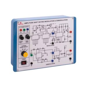
Amplitude Shift Keying Modulation and Demodulation
This Instrument is designed to demonstrate the method to transmit signals via. Electromagnetic transmission and to study the Amplitude shift keying Modulation and Demodulation. The whole instrument is placed in the plastic moulded box and 2 mm banana plug leads are provided for modulation and demodulation connections.
Technical Specification:-
- Fixed Output DC Regulated Power Supply of ±12, +5 volts.
- 100KHz with 5 Vpp amplitude (Approx.) for carrier frequency.
- In-built square wave data generator.
- Circuit diagrams for Modulator and Demodulator are printed on the milky white top panel.
PH93105 -
Electronics
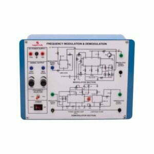
Frequency Modulation and Demodulation
This Instrument is designed to demonstrate the method to transmit signals via. Electromagnetic transmission and to study Frequency Modulation and Demodulation. The whole instrument is placed in the plastic moulded box and 2 mm banana plug leads are provided for modulation and demodulation connections.
Technical Specification:-
- Fixed Output DC Regulated Power Supply of ±12 Volts.
- Built Modulating signal Generator of 2 KHz and 4 KHz selectable with a toggle switch with Amplitude to 3V peak to peak approximately.
- Circuit diagrams for Modulator and Demodulator are printed on the milky white top panel.
PH93110 -
Electronics
Frequency Shift Keying Modulation and Demodulation
This Instrument is designed to demonstrate the method to transmit signals via. Electromagnetic transmission and to study the Frequency Shift Keying Modulation and Demodulation. The whole instrument is placed in the plastic moulded box and 2 mm banana plug leads are provided for modulation and demodulation connections.
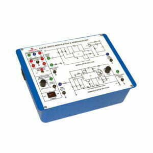
PH93115 -
Electronics
Pulse Width Modulation and Demodulation
This Instrument is designed to demonstrate the method to transmit signals via. Electromagnetic transmission and to study the Pulse Width Modulation and Demodulation. The whole instrument is placed in the plastic moulded box and 2 mm banana plug leads are provided for modulation and demodulation connections.
Technical Specification:-
- Built-in IC-based DC Regulated Power supply ±12 V, +5 V.
- Four-level Built carrier pulse Output.
- Frequency Range: 8 KHz, 16 KHz, 32 KHz, 64 KHz Amplitude: 5 Vpp approx.
- Built-in sine wave Audio Frequency Function Generator for modulating signal.
Frequency Range: 1 KHz and 2 KHz selectable with a toggle switch.
Amplitude : 0-10 Vpp and 0-4 Vpp approx. - The circuit Diagram for Modulation and Demodulation is printed on the milky white top panel.
PH93120 -
Electronics
Phase Shift Keying Modulation and Demodulation
This Instrument is designed to demonstrate the method to transmit signals via. Electromagnetic transmission and to study the Phase Shift Keying Modulation and Demodulation. The whole instrument is placed in the plastic moulded box and 2 mm banana plug leads are provided for modulation and demodulation connections.
Technical Specification:-
- Fixed Output DC Regulated Power Supplies of ±12V and ±5V.
- Built Carrier wave Generator (Sine Wave) of 5V peak-to-peak amplitude, 22 KHz ±5% Frequency range with output on sockets.
- Built-in Data Generator using IC 7490 with four modulating signal outputs on sockets.
- IC TL084 & IC 7486 are used for the PSK demodulator.
- The circuit diagram is printed on the milky white top panel and important connections are brought out on the sockets.
PH93125 -
Electronics
Micro Controller Development Board
The Microcontroller Development board is designed to train Engineers about structural design, and instructions and utilize the 8051 microcontroller Board. A 40-pin ZIF socket for easy insertion of an 89 series microcontroller with four 10 Pin FRC connectors is provided on the board. Outputs from the I/O port from the microcontroller are available on FRC connectors which can be easily connected with different modules. Microcontroller Development Board consists of EEPROM with 4K memory changeable with more RTC DS1307 with 32 KHz crystal with battery backup One 12V stepper motor with drivers.
- One 16 x 2 LCD display.
- 8 Output LED indicators.
- 4 multiplexed 7-segment display.
- 8 single-bit toggle switches.
- 4 x 4 matrix keyboard.
- Single Channel ADC with potentiometer and provision of external inputs.
- RS 232 serial communication.
- One 12V DC motor driver.
PH93130 -
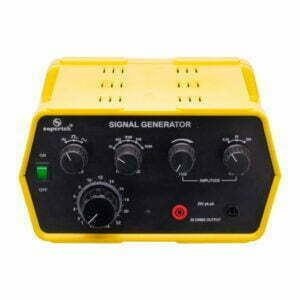
Electronics
Signal Generator
An audio frequency Generator is a versatile instrument providing sine, square & triangular wave functions over a wide range from 2 – 220 KHz in decade ranges. The amplitude of the waveforms can be varied from 20mV to 20V pk to pk about zero level with the help of three-step coarse control and fine control. The complete unit is enclosed in an attractive metal cabinet without BMC cable.
PH93205 -
Electronics
Signal Generator, Digital
An audio frequency generator is a versatile instrument providing sine, square & triangular wave functions over a wide range from 2 to 220 KHz in decade ranges. The amplitude of the waveforms can be varied from 20 mV to 20 V peak to peak at about zero level with the help of three-step coarse control & fine control. The complete unit is enclosed in an attractive metal cabinet and operates on a 24V DC adapter.
PH93205D -
Electronics
Signal Generator
1Hz to 100KHz in five-decade ranges selected by rotary switch named as frequency Multiplier. Sine Triangular and Square waveforms selected by push switch with LED indication. The output signal is 0-3.5 V RMS (10V peak to peak) open circuit continuously control with an uncalibrated amplitude control knob. Mains rocker switch with indicator Light. Signal Generator is versatile for general laboratory use; the output signal is adjustable with the combination of Freq. multiplier and set frequency dial with a low level of distortion. Output Voltage is continuously variable with selector range 1V and 10V. There is two pair of output safety sockets. One for CRO output (experiment for amplification, filter, etc.) and another pair of sockets to speaker to drive a speaker and to demonstrate the audio signal frequency range 20Hz to 20KHz without BMC cable.
PH93210