-
Electronics
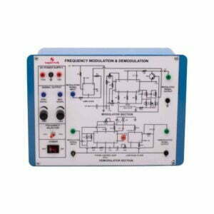
Frequency Modulation and Demodulation
This Instrument is designed to demonstrate the method to transmit signals via. Electromagnetic transmission and to study Frequency Modulation and Demodulation. The whole instrument is placed in the plastic moulded box and 2 mm banana plug leads are provided for modulation and demodulation connections.
Technical Specification:-
- Fixed Output DC Regulated Power Supply of ±12 Volts.
- Built Modulating signal Generator of 2 KHz and 4 KHz selectable with a toggle switch with Amplitude to 3V peak to peak approximately.
- Circuit diagrams for Modulator and Demodulator are printed on the milky white top panel.
PH93110 -
Electronics
Frequency Shift Keying Modulation and Demodulation
This Instrument is designed to demonstrate the method to transmit signals via. Electromagnetic transmission and to study the Frequency Shift Keying Modulation and Demodulation. The whole instrument is placed in the plastic moulded box and 2 mm banana plug leads are provided for modulation and demodulation connections.
PH93115 -
Electronics
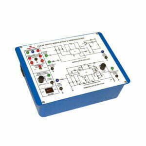
Pulse Width Modulation and Demodulation
This Instrument is designed to demonstrate the method to transmit signals via. Electromagnetic transmission and to study the Pulse Width Modulation and Demodulation. The whole instrument is placed in the plastic moulded box and 2 mm banana plug leads are provided for modulation and demodulation connections.
Technical Specification:-
- Built-in IC-based DC Regulated Power supply ±12 V, +5 V.
- Four-level Built carrier pulse Output.
- Frequency Range: 8 KHz, 16 KHz, 32 KHz, 64 KHz Amplitude: 5 Vpp approx.
- Built-in sine wave Audio Frequency Function Generator for modulating signal.
Frequency Range: 1 KHz and 2 KHz selectable with a toggle switch.
Amplitude : 0-10 Vpp and 0-4 Vpp approx. - The circuit Diagram for Modulation and Demodulation is printed on the milky white top panel.
PH93120 -
Electronics
Phase Shift Keying Modulation and Demodulation
This Instrument is designed to demonstrate the method to transmit signals via. Electromagnetic transmission and to study the Phase Shift Keying Modulation and Demodulation. The whole instrument is placed in the plastic moulded box and 2 mm banana plug leads are provided for modulation and demodulation connections.
Technical Specification:-
- Fixed Output DC Regulated Power Supplies of ±12V and ±5V.
- Built Carrier wave Generator (Sine Wave) of 5V peak-to-peak amplitude, 22 KHz ±5% Frequency range with output on sockets.
- Built-in Data Generator using IC 7490 with four modulating signal outputs on sockets.
- IC TL084 & IC 7486 are used for the PSK demodulator.
- The circuit diagram is printed on the milky white top panel and important connections are brought out on the sockets.
PH93125 -
Electronics
Micro Controller Development Board
The Microcontroller Development board is designed to train Engineers about structural design, and instructions and utilize the 8051 microcontroller Board. A 40-pin ZIF socket for easy insertion of an 89 series microcontroller with four 10 Pin FRC connectors is provided on the board. Outputs from the I/O port from the microcontroller are available on FRC connectors which can be easily connected with different modules. Microcontroller Development Board consists of EEPROM with 4K memory changeable with more RTC DS1307 with 32 KHz crystal with battery backup One 12V stepper motor with drivers.
- One 16 x 2 LCD display.
- 8 Output LED indicators.
- 4 multiplexed 7-segment display.
- 8 single-bit toggle switches.
- 4 x 4 matrix keyboard.
- Single Channel ADC with potentiometer and provision of external inputs.
- RS 232 serial communication.
- One 12V DC motor driver.
PH93130 -
Electronics
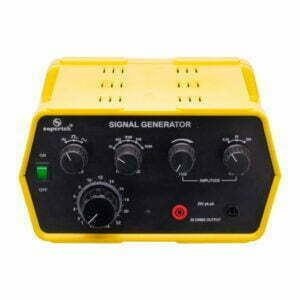
Signal Generator
An audio frequency Generator is a versatile instrument providing sine, square & triangular wave functions over a wide range from 2 – 220 KHz in decade ranges. The amplitude of the waveforms can be varied from 20mV to 20V pk to pk about zero level with the help of three-step coarse control and fine control. The complete unit is enclosed in an attractive metal cabinet without BMC cable.
PH93205 -
Electronics
Signal Generator, Digital
An audio frequency generator is a versatile instrument providing sine, square & triangular wave functions over a wide range from 2 to 220 KHz in decade ranges. The amplitude of the waveforms can be varied from 20 mV to 20 V peak to peak at about zero level with the help of three-step coarse control & fine control. The complete unit is enclosed in an attractive metal cabinet and operates on a 24V DC adapter.
PH93205D -
Electronics
Signal Generator
1Hz to 100KHz in five-decade ranges selected by rotary switch named as frequency Multiplier. Sine Triangular and Square waveforms selected by push switch with LED indication. The output signal is 0-3.5 V RMS (10V peak to peak) open circuit continuously control with an uncalibrated amplitude control knob. Mains rocker switch with indicator Light. Signal Generator is versatile for general laboratory use; the output signal is adjustable with the combination of Freq. multiplier and set frequency dial with a low level of distortion. Output Voltage is continuously variable with selector range 1V and 10V. There is two pair of output safety sockets. One for CRO output (experiment for amplification, filter, etc.) and another pair of sockets to speaker to drive a speaker and to demonstrate the audio signal frequency range 20Hz to 20KHz without BMC cable.
PH93210 -
Electronics
Signal Generator, Digital
This signal generator is a useful test instrument capable of generating multiple waveforms and offers excellent wave shape, signal linearity, waveform symmetry, and frequency range with a selection of sine, triangular and square waves and amplitude variable 10 V peak to peak. 1 Hz to 100 kHz in five-decade ranges selected by rotary switch named as a frequency multiplier. Sine, triangular and square waveforms are selected by push switch with LED indication. The output signal is 0-3.5 Vrms (10 V peak to peak) open circuit continuously control with an uncalibrated amplitude control knob.
Mains rocker switch with indicator Light. Signal Generator is versatile for general laboratory use; the output signal is adjustable with the combination of frequency multiplier and set frequency dial with a low level of distortion. Set frequency is displayed on a 4 seven-segment display. Output Voltage is continuously variable with selector range 1V and 10V. There is two pair of output safety sockets. One for CRO output (experiment for amplification, filter, etc.) and another pair of sockets to speaker to drive a speaker and to demonstrate the audio signal frequency range 20 Hz to 20 KHz without BMC cable.PH93210D -
Electronics
Advanced Signal Generator
An advanced signal generator is a versatile unit that has both high and low impedance outputs, making the unit ideal for driving vibration generators and loudspeakers whilst an internal speaker (which can be turned on or off) can be used to demonstrate the human hearing range. The unit also includes an auxiliary input for amplifying external sound signals. A separate headphone socket lead and 4mm adapter are also available to transfer the various sound signals into the signal generator.
- Frequency range: 1 to 110 kHz in a 5-decade range
- Waveforms: Sine, square or triangular.
- Digital LED display
- Low impedance output x watts: Perfect for driving vibration generators or loudspeakers
- High impedance output: Can be attenuated by a factor of 10 or 100
- A built-in loudspeaker (can be switched off)
- Internal short circuit protection
- Amplitude and frequency modulation options
- Input impedance: 1MW Frequency response 1Hz to 100kHz, -3dB
- Output power: 4W into 4W load
PH93210G -
Electronics
Oscilloscope
This Oscilloscope is corresponding to horizontal with small in size. The bandwidth of the Y axis is DC 10MHz and the deflection factor is 5mV 5V/div. It can be up to 50V/div. using the 10:1 probe. The sweep deflection factor is 0.1μs/div.
- Single Channel Single Trace Oscilloscope.
- Bandwidth: 10 MHz.
- Confirms EN61010-1 (1993) and EN-IEC61326-1(1997).
- Wide measurement.
- High sensitivity and trigger lock.
- Sweep switch adopts digital code switch and accuracy.
- Proper to use in colleges and for engineers and technicians.
- The deflection factor is 5 mV – 5 V / div in a 1-2-5 Sequence in 10 steps.
- Accuracy: ±5 %.
- Maximum Input Voltage: 400Vpk.
- The sweep deflection factor is 0.1 us/div to 0.1s/div.
- Accuracy: ±5%.
- Trigger Sensitivity: INT:1.5 div EXT: 0.3V.
- Trigger mode: INT, EXT, LINE, TV.
- Trigger Sweep Mode: NORM, AUTO, TV. LOCK.
- Calibration Signal: 0.5 V Square wave of 1 kHz.
- CRT Effective working Area: 8 x 10 div. 1 div = 6 mm.
- Auxiliary Power Supply: 220V AC 50Hz.
PH93215 -
Electronics
Oscilloscope
This is a portable type of Oscilloscope for two traces. The bandwidth is 0-20 MHz. The instrument is easy operation with comfortable controls. Its reasonable structure and technology make it convenient to repair and calibrate.
- Dual Trace Dual Channel Oscilloscope with Component Test Facility.
- Bandwidth: 20 MHz.
- Full bandwidth sweeping circuit is used in the sweeping system.
- The flexible and convenient triggering mode has the functions for selecting signals from one channel or triggered by Ext signals.
- ALT triggers to observe signals from two irrelative channels.
- The instrument has the functions of TV-H/TV-V synchronization and trigger-lock to observe all kinds of signals stably.
- From the terminal for trigger input, CH1 and CH2 signals can be output along with the triggering channel to connect the external frequency counter.
- Y deflection operation: Y1, Y2, ALT, CHOP, ADD, mode X-Y.
- Vertical Deflection: 5 mV/Div to 20V/Div in factor 1-2-5 sequence in 12 steps.
- Rising time: < 18 nS.
- Maximum Input Voltage: 400V (DC + ACp-p).
- Triggering Source: Y1, Y2, ALT, POWER, EXT.
- Trigger Coupling: AC/DC (EXT), NORM / TV-H, TV-V.
- Horizontal Sweep Mode: AUTO, TRIG, LOCK, SINGLE.
- Sweep time factor: 0.1 uS / div to 0.2 s / div in 1-2-5 sequence in 20 steps.
- Magnification: x10.
- X-Y Mode input: X-Axis Y1 and Y-Axis Y2.
- Z Axis minimum input level: TTL Level.
- Component Test Facility.
- Calibration Signal: Square wave of 0.5 V at 1 kHz.
- CTR Display size: 8 cm x 10 cm.
- Auxiliary Power Supply: 220V 50Hz AC.
PH93220 -
Electronics
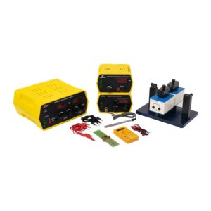
Hall Effect Experiment
Introduction
The resistivity measurements of semiconductors cannot reveal whether one or two types of carriers are present; nor distinguish between them. However, this information can be obtained from Hall Coefficient measurements, which are also basic tools for the determination of carrier density and mobility in conjunction with resistivity measurement.Working
When a conductor through which current is flowing, is placed in the magnetic field, a potential difference is generated between two opposite edges of the conductor in the direction mutually perpendicular to both the field and the conductor. This potential developed is Hall voltage and the phenomenon is called Hall Effect. In the experimental setup, the crystal mounted on PCB is placed perpendicular to the pole pieces. A constant current is passed through the crystal using the constant current source. Magnetic field is produced by electromagnet operated by 0 – 12 V DC, 5 A power supply. Magnetic field intensity is measured by gauss meter with gauss probe. A Hall voltage thus produced is measured by the multimeter.The following parts are included in Hall Effect Experiment:
PH93225H Hall Probe
PH61033D/5 Advanced Power Supply
PH93225E Electromagnet Setup
PH61500 Constant Current Power Supply
PH93225G Digital Gauss Meter
PH64505 3 ½ Digit Multimeter
PH93225 Hall Effect Experiment (Complete)PH93225 -
Electronics
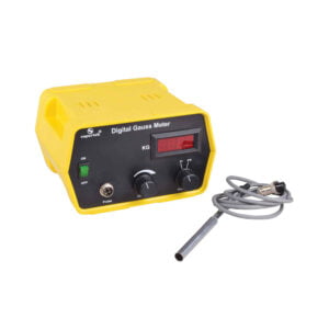
Digital Gauss Meter
Digital Gauss meter works on the principle of the Hall Effect in semiconductors. When a semiconductor with current flowing in one direction is introduced perpendicular to a magnetic field a voltage is produced at right angles to the current path. The magnitude of this voltage is proportional to the intensity of the magnetic field. This voltage is called Hall Voltage. This Hall voltage is amplified and calibrated as the magnetic field.
Specifications:
- Range: 0-2 KG & 0-20 KG.
- Resolution: 1 G at 0-2 KG range.
- Display: 3½ digit LED.
- Power Supply: 220 V, ±10%, 50 Hz AC.
- Transducer: Hall probe-In As.
PH93225G -
Electronics
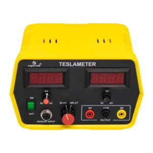
Teslameter
The tesla meter is used for the measurement of flux densities in steady magnetic fields. The unit includes a Hall sensor probe for measuring axial and tangential magnetic fields up to 20mT. The magnetic field probe is provided with a metric scale for measuring distances. In addition to having a digital display, the unit outputs a voltage proportional to the magnetic field which can be measured with a data logger, XY-recorder, or analog multimeter.
PH93240 -
Accessories
Energy Band Gap Apparatus
The energy band Gap Measuring Instrument is used to find the energy band gaps of the different semiconductor diodes and LEDs. The setup comes with a temperature meter, an in-built heating element with an ON/OFF toggle switch, and the following diodes and LEDs (IN4007, Germanium Diode, Green LED, and Blue LED) which can be selected by a rotary switch. Ammeter and voltmeter are connected externally to the instrument.
Specifications
Input Voltage – 12V DC
Current Rating – 5 A Max.
Heater Power – 40 Watt
Temperature Range- 0 – 110⁰CPH94002 -
Accessories
Planck Constant Apparatus
Planck’s Constant Measuring Instrument is used to determine Planck’s constant, “h” using LEDs. The setup comes with a voltmeter, temperature meter, a heating element with an ON/OFF toggle switch, and the following LEDs (Amber, Blue, Yellow, Red, and Green LED) which can be selected by a rotary switch. Ammeter can be connected externally to the instrument.
Specifications
Input Voltage – 12V DC.
Current Rating – 5 A Max.
Heater Power – 40 Watt.
Temperature Range- 0 – 110⁰C.PH94004