-
Electronics
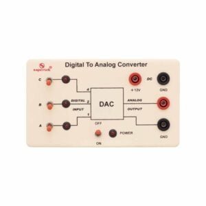
Analog to Digital Converter
The ADC unit converts an analog signal to a digital signal. When a variable voltage is applied to the input terminals it is converted into a digital output. Therefore, a 3-volt input will correspond to binary 11, and 7 volts will correspond to binary 111. A low-frequency AC input signal can be converted into a changing digital value. Use on its own or combined with the DAC to decode back into a stepped analog voltage.
PH92370A -
-
Electronics
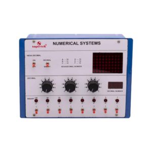
Numerical System
This panel is used to demonstrate the number systems such as binary, decimal, and hexadecimal numbers. Toggle switches are used to activate the displays showing the particular number entered. Input may be entered either as decimal or binary numbers with a toggle switch for mode selection. Decimal numbers are shown on a three-digit seven-segment LED display. Operates on 220V.
PH93002 -
Electronics
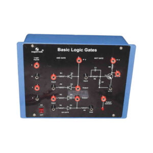
Logic Gates Trainer
Logic Gates Trainer is a self-training course in basic digital electronics and is the first step to understanding the fundamentals of any computer. It enables the student to understand AND, OR, NOT, NAND & NOR Gates and in the process to make connections. Supplied with user’s manual.
PH93005 -
Electronics
Logic Gates Trainer
Logic Gates Trainer has been designed to study logic gates and applications. This trainer board is designed to verify the truth table of various logic functions, to prove De-Morgan’s theorem, Half adder, and Full adder by using logic gates. The board is absolutely self-contained and requires no additional apparatus. 12 V / 1 A DC adaptor is required to operate it.
PH93005B -
Electronics
Logic Gate Circuit Trainer
Study and verification of flip flops, counters, shift registers, encoders, decoders, multiplexers, and de-multiplexers. Consists of 8 debounced logic inputs, 8 red LED output indicators, +5 V DC (1 A) regulated, short circuit and overload protected power supply, and 1 Hz mono shot clock pulse. All the ICs and components have been placed inside the cabinet and connections brought out at 4 mm sockets.
PH93007 -
Electronics
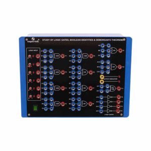
Study of Logic Gates, Boolean Identities and Demorgan’s Theorems
To verify the truth table of 3 input AND gate, OR gate, NAND gate, NOR gate, single input NOT gates, Boolean expressions, and Demorgan’s theorems. Consists of 5V d. c. regulated power supply, 4 push-to-ON switches provided for selecting logic ‘1’ and logic ‘0’, 2 Red LED output indicators, circuit diagram printed for 5 OR, 5 AND, and 4 NOT gates and their respective IC’s placed inside the cabinet and connections brought out at sockets.
PH93010 -
Electronics
Operation Amplifier Kit
To study Operational Amplifier Characteristics and Applications. Consists of 3 D. C. regulated power supplies of 0 – 5 V Continuously variable, ± 15 V D. C. regulated power supply, Sine, Square, Triangular wave outputs, one Bread board having two main strips and two distribution strips. Complete with two dual-range meters and necessary components.
PH93015 -
Electronics
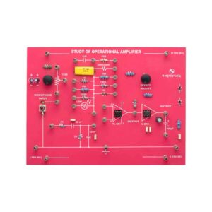
Study of Operation Amplifier
To demonstrate the function of the operational amplifier using TL081 and L272 with discrete components with different values of resistors, and capacitors. Input can be applied from the microphone and LDR. Offset null control is also provided. Output can be fed through the power amplifier into a loudspeaker.
PH93020 -
Electronics
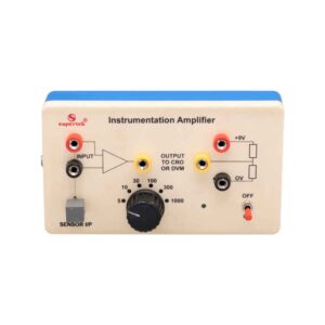
Instrumentation Amplifier
An instrumentation amplifier is a switched gain precision operational amplifier. This is used for precise and accurate, low-noise differential signal acquisition. 4mm sockets are used for the input signal. It can be interfaced with a wide range of sensors. It can take small voltage changes from a sensor and make those changes large enough to be measured using CRO. It is not able to drive a low-impedance load such as a loudspeaker or relay. The output can be read on CRO. A digital multimeter may also be used to read the output. With the switched gain of 5 to 1000, it can handle signal inputs over a very wide range making it suitable for almost all applications.
PH93020B -
Electronics
Linear IC Trainer
This trainer consists of :
- The regulated power supply of ± 12 V / 250 mA.
- Variable 0 to ±5 V / 250 mA.
- Sine wave oscillation of 1 KHz.
- Digital Voltmeter of 0-20 V DC, LCD display, 3 ½ Digit.
- The functional diagram of IC 741 is printed with 2 mm sockets.
- One extra 8-pin IC Base with 2 mm sockets.
- Potentiometer of 10K Ohms.
- Required Resistance and Capacitances mounted on board.
- Interconnection leads and manual to perform 15 experiments on IC 741 e.g. inverting, non-inverting, summing, difference, multiplier, differentiator, integrator, etc.
PH93025 -
Electronics
Digital Trainer Using NAND Gates
Complete with a Regulated power supply of + 5V/500 mA. Provided with 4 Logic input switches (bounceless) and 4 LED Indicators (Buffered).
Functional diagram of:-
- 3 Input NAND – 6 No.
- 4 Input NAND – 4 No.
- 1 Input NOT Gates – 4 No. is printed on board.
- 12 Interconnection Leads and User’s Manual are provided.
PH93027 -
Electronics
Half Wave/Full Wave and Bridge Rectifier Apparatus
Objective: To study the Efficiency and Ripple factor in the case of Half wave, Full wave, and Bridge rectifiers on the application of load and filters.
Features: The instrument comprises of AC Power Supply, 3 meters to measure Output Voltage, Output Current, and ripple factor on an electronic AC Voltmeter, 4 PN Junction Diodes, a Filter Circuit kit, load Resistances selectable using a band switch, and all important connections point at 4mm Sockets.
Optional Acc : Digital AC millivoltmeter.PH93032 -
Electronics
LCR Resonance Apparatus
Objective: To plot Frequency Vs. Current Characteristics of LCR circuit when connected in series or in parallel.
Features: The instrument comprises of 3 Resistances, 3 Capacitors, and 1 Inductance connected inside and connections brought out at Sockets. 2 AC moving coil meters to measure voltage and current.
Optional Acc.: Audio Frequency Function Generator.PH93035 -
Electronics
Fiber Optics Communication Set
Objective: To construct an optical transmitter and transmission the signal through a Fiber Optics Cable. To construct an Optical Receiver and study the Attenuation of Signal when transmitted from Transmitter to the Receiver end. Analog and Digital links can also be studied as this unit is complete with Sine and Square Waves. Bending losses can also be studied.
Features: The instrument comprises of Microphone Preamplifier stages consisting of MIC (Microphone), Preamplifier, and Amplifier (Voice is converted to an electrical signal and then amplified) and fed to an LED (Transmitter) and then through a fiber cable, the signal is sent to Photodetector (Transistor) and again amplifier and output are sent to Speaker Unit. A power supply of +6 VDC is used in Amplifier ckt. 2 No. Fiber Optics cables are provided (one of them is 50 cm long and the other is 100 cm long). One more fiber cable of 50mm length having a connector at one end is also provided. Connectors at both ends of the fiber cable are provided for insertion in sockets provided on the front panel. Bending losses can also be studied in long wires.
Standard: MIC with a 2-meter long lead and a Speaker 4″, 4 ohms are mounted in a vertical box.
Accuracy: with 1 meter-long connecting leads. 2 No. Fiber optic cables having lengths of 50 cm and 100 cm are provided.
Optional: Digital multimeter (3 1/2 Digit, Big size Display) This model also includes a Digital Multimeter and wooden frame for measurement of Numerical aperture i.e. complete in all respect including the facility for the measurement of numerical aperture.
PH93040 -
Electronics
Amplitude Modulation and Demodulation
The instrument is designed to demonstrate the method to transmit signals via. Electromagnetic transmission. It is still used in radio systems to transmit audio signals although it has lesser in popularity compared to FM (Frequency Modulation) due to its lower signal-to-noise ratio.
Technical Specification:-
- IC-based DC regulated power supply ±12 V / 500 mA.
- Audio frequency 1 KHz / 0-2 Vpp for modulating signal 455 KHz / 2.5 Vpp approx. for Carrier Frequency.
PH93100 -
Electronics
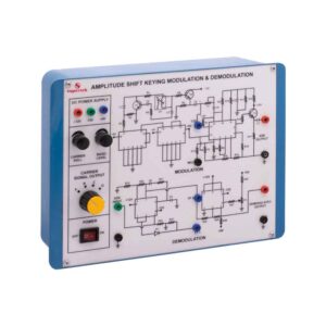
Amplitude Shift Keying Modulation and Demodulation
This Instrument is designed to demonstrate the method to transmit signals via. Electromagnetic transmission and to study the Amplitude shift keying Modulation and Demodulation. The whole instrument is placed in the plastic moulded box and 2 mm banana plug leads are provided for modulation and demodulation connections.
Technical Specification:-
- Fixed Output DC Regulated Power Supply of ±12, +5 volts.
- 100KHz with 5 Vpp amplitude (Approx.) for carrier frequency.
- In-built square wave data generator.
- Circuit diagrams for Modulator and Demodulator are printed on the milky white top panel.
PH93105